MECHANICAL — CFD AND ENERGY · LONDON, UK (SYNTHETIC DATA HALL)
Data Centre CFD Analysis
Automated CFD and annual-energy comparison of two cooling layouts for a small synthetic data-hall test room (DC-00, 4 racks x 10 kW). Native CFD converged for both designs and all rack inlets stayed within 18-27 °C with 12.5 % less supply air, but the mass, energy-balance, boundary, plausibility and mesh gates failed, and the annual saving rests on assumed equipment models. Accepted by the work as an automation proof of concept, not an engineering-validated energy-saving study.
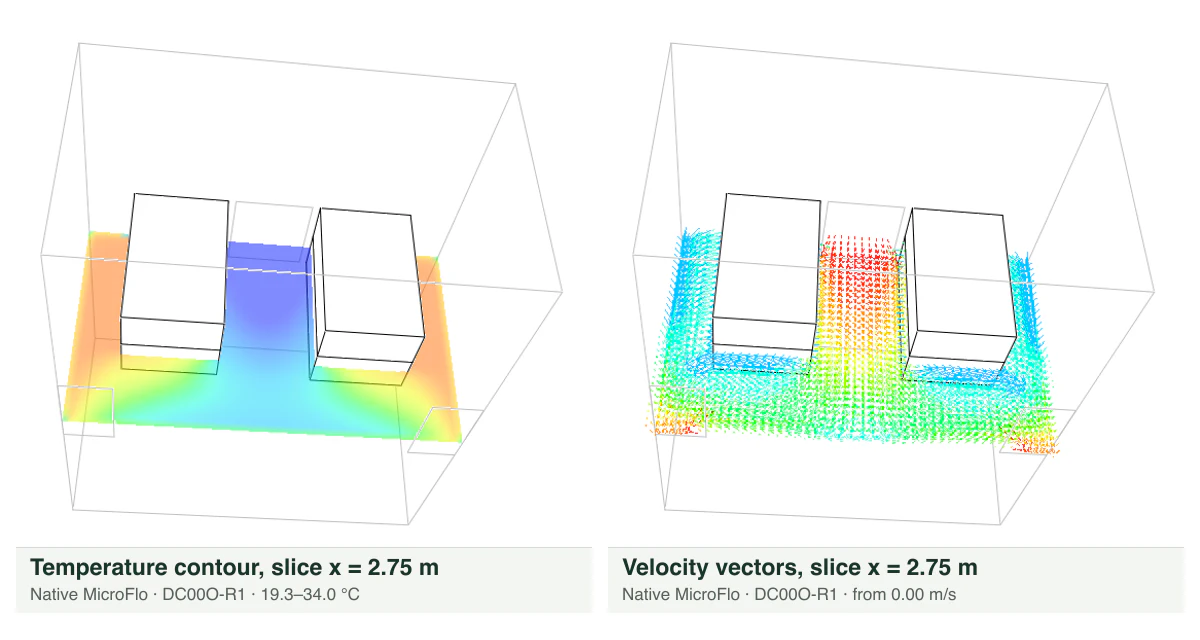
Native CFD of a synthetic data hall: 12.5 % less supply air with rack inlets still 18-27 °C - not engineering validated
Max rack inlet (baseline / optimised)
21.62 / 21.49 °C
Supply air
−12.5 %
Modelled cooling-energy saving
12.7 % (upper bound, assumed equipment)
Validation gates passed
3 of 8
- Discipline
- Mechanical — CFD and energy
- Location
- London, UK (synthetic data hall)
- Building
- Data centre (synthetic test room)
- Stage
- Feasibility study (automation proof of concept)
- Verification status
- NOT ENGINEERING VALIDATED — native CFD converged; validation gates partly failed
- Engineering approval
- OUTSTANDING — no engineer review or approval recorded
Objectives
- Drive dynamic simulation, CFD set-up, meshing, solving, validation, variants, annual energy and reporting end to end without manual operator steps.
- Start from the smallest geometry and converge the baseline before any variant.
- Compare a baseline layout (supply 1.20 x IT airflow) with an optimised layout (1.05 x IT airflow, hot-aisle extracts) on rack inlet temperatures and annual cooling-system electricity.
- Compute the engineering status from validation gates so that no report can claim more than the evidence shows.
Overview
Native CFD runs converged for both designs, but the validation gates for mass conservation, energy balance, boundary read-back, physical plausibility and mesh sensitivity FAILED. Engineering approval is OUTSTANDING: no engineer review or approval is recorded.
An automation proof of concept on a small synthetic data-hall test room (DC-00, London): Hexanta prepared the inputs, drove a commercial dynamic-simulation and CFD package end to end without manual steps, parsed the solver outputs and applied its own validation gates. A baseline cooling layout (floor supply 1.20 x IT airflow, one ceiling extract above the cold aisle) was compared with an optimised layout (1.05 x IT airflow, two extracts over the hot aisles) for rack inlet temperatures and annual cooling-system electricity.
At a glance
- Case
- DC-00 synthetic test room, 6.0 x 4.8 x 3.0 m, 4 racks x 10 kW
- Designs
- DC00B baseline / DC00O optimised (12.5 % less supply air)
- Max rack inlet
- 21.62 °C baseline, 21.49 °C optimised (solver cell monitors)
- Modelled energy difference
- 17,982 kWh/yr (12.7 %) - SIMULATED WITH ASSUMED EQUIPMENT MODEL, upper bound
- Computed status
- NOT ENGINEERING VALIDATED
- Engineering approval
- OUTSTANDING — no engineer review or approval recorded
IESVE 2026 (ApacheSim and MicroFlo) under a trial licence for internal evaluation only; the licence expired on 2026-10-25. Nothing was re-simulated for this case study: it presents results preserved in the evidence store.
Verification summary
27 recorded results · 15 from the native tool · 11 PASS · 3 PARTIAL · 13 FAIL
Native evidence and completeness matrix → Verified downloads →
Engineering findings
- Both final CFD runs converged natively: DC00B-R6 after 2,599 iterations and DC00O-R1 after 653, all 7 residuals at 1e-5.
- All monitored rack inlets stayed within 18-27 °C in both designs: maximum 21.62 °C baseline, 21.49 °C optimised, 21.53 °C on the refined mesh.
- The defensible statement is "no degradation with 12.5 % less supply air", not "cooler inlets".
- The baseline flow field shows the floor jet short-circuiting to the ceiling extract above the cold aisle.
- Annual simulations: 141,449 kWh/yr (baseline) vs 123,467 kWh/yr (optimised) cooling-system electricity; modelled difference 17,982 kWh/yr (12.7 %), SIMULATED WITH ASSUMED EQUIPMENT MODEL, upper bound (n = 2 gives 12,768 kWh/yr).
- The independent energy audit matches IESVE and excludes Apache's whole-building difference (32,368 kWh/yr), which counts the fan saving twice.
- DC-01 (synthetic 20 x 12 x 4 m hall, 100 kW): annual simulation N1F accepted at software level, 352,337 kWh/yr cooling-system electricity; N1D and N1E rejected by the gates.
- The computed study status is NOT ENGINEERING VALIDATED.
Conclusions
- As an automation proof of concept the study succeeded: Hexanta drove the CFD set-up, solving, validation gates, annual energy and reporting end to end, and both final native CFD runs converged (DC00B-R6, DC00O-R1).
- With 12.5 % less supply air every monitored rack inlet stayed within 18-27 °C (maximum 21.62 °C baseline, 21.49 °C optimised): the defensible statement is no degradation, not cooler inlets.
- The study is NOT ENGINEERING VALIDATED: the mass, energy-balance, boundary, plausibility and mesh gates failed, and the 12.7 % (17,982 kWh/yr) cooling-energy difference is an upper bound SIMULATED WITH ASSUMED EQUIPMENT MODEL, not a validated saving.
Limitations
- Actual equipment performance curves are not modelled: SEER 4.0, SFP 1.5 W/(l/s) and fan law n = 3 are ASSUMED.
- Racks are 0 W blocks with face boundaries and an imposed exhaust temperature (heat output follows inlet temperature; uniform faces; no bypass or leakage).
- No complete CFD mass and energy balance: no solver flow report or field export; the energy balance is estimated from point samples only.
- Baseline mesh independence not assessed (single grid); optimised top inlets not monotonic over three grids.
- No independent solver benchmark or measured case.
- The annual model is a single zone held at 28 °C and responds to airflow only through fan power; annual cooling energy is not validated.
- Boundary values were read back from screenshots and table cells only, not programmatically.
- The 18-27 °C inlet range comes from a public summary; the licensed current edition is not held.
- The tariff (0.25 GBP/kWh) is an ASSUMED placeholder.
- IESVE 2026 trial licence for internal evaluation only (expired 2026-10-25); commercial use would need a commercial licence and the vendor's written terms.
What this case study does not claim
- Engineering validation, verification, review, approval or sign-off of any result.
- The 17,982 kWh/yr (12.7 %, GBP 4,495/yr) figure as an achieved or validated saving; it is an upper bound with an assumed equipment model and tariff.
- That the optimised design gives cooler rack inlets.
- That mass or energy balance, or full mesh independence, was demonstrated.
- Any CFD for DC-01, or any modelling of a real data centre, client or site: all data are synthetic.
- Compliance with any licensed design guideline or standard.
- A Hexanta CFD solver: the CFD was solved by IESVE MicroFlo; Hexanta prepared inputs, drove the software, parsed outputs and applied the gates.
- Production-scale or commercially licensed automation: the runs were serial GUI automation on one test machine under a trial licence.
- Apache's whole-building total difference (32,368 kWh/yr) as a saving.
Sanitised derivative of preserved evidence (cfd-DC00-20261024-r2, cfd-DC01-N1-DSM-20261024). Nothing was re-simulated. Screenshot crops are static images of the native viewer; plots and the report contain only values read from the evidence. · Pack cfd-data-centre-r2 (built 2026-10-25); every file is checked against its SHA-256 before it is shown.